

A TALE OF RADIALS

Vertical antenna systems, losses, and efficiency
The more interesting, and perhaps more important part of the story is the other half of the antenna system: the ground, for it is the ground that acts as the “other half” of the antenna. In a world where we could have a flat copper disk sitting below our vertical antenna extending off to the horizon, we would not have too many concerns about our “ground.” Such as ground would have very low electrical resistance, about that of copper wire, and would, therefore, carry our RF current well. And, as we know, RF current is what makes RF waves.
When we evaluate an antenna we often compare it to a properly hung dipole. Dipoles are very good antennas, and if deployed properly, they can be very efficient. A dipole hung high in the air using a low-resistance wire can be as much as 97% efficient. What do we mean by that? We mean that the total losses in our antenna from wire resistance, and any reactance (an opposition to AC current flow) is less than 3% of the total resistance. Here’s the definition of antenna efficiency:
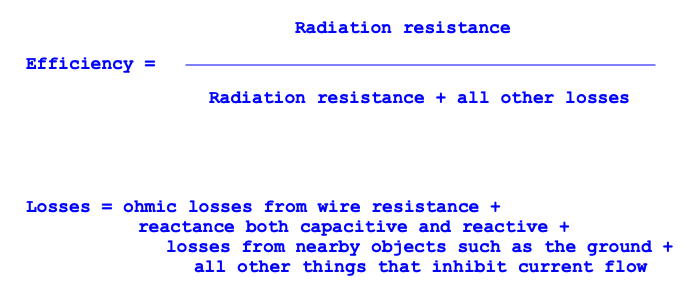
Figure 1. Efficiency calculation for an antenna
Let’s talk about ohmic losses. Consider that AWG 16 wire has about 0.4-ohms of resistance per one-hundred feet of length. It isn’t zero, but it isn’t much! And that loss contributes to the total losses in the system. While we’re at it, connectors might induce a small loss (fractions of an ohm) but even these small losses can be relatively large in, say, a magnetic loop system where the radiation resistance might also be just a fraction of an ohm.
A quarter-wave vertical antenna uses the ground as the other half of the antenna. The vertical radiator is one half; the ground is the other. The system doesn’t work without the ground side. But, unlike that big copper disk we talked about above, the typical ground doesn’t carry current well, and current (the movement of the charge) is what makes the antenna emit signals. The higher the current, the stronger the signal. So, we should do everything we can to make our antenna system conduct as much current as possible. We need to find a way to lower the losses in the ground to maximize current.
The resistance and conductivity of the ground
Here’s small map of the United States showing the variations.
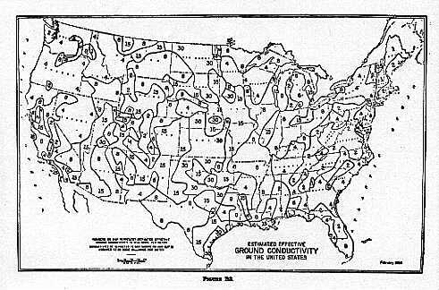
Figure 2. US soil conductivity map
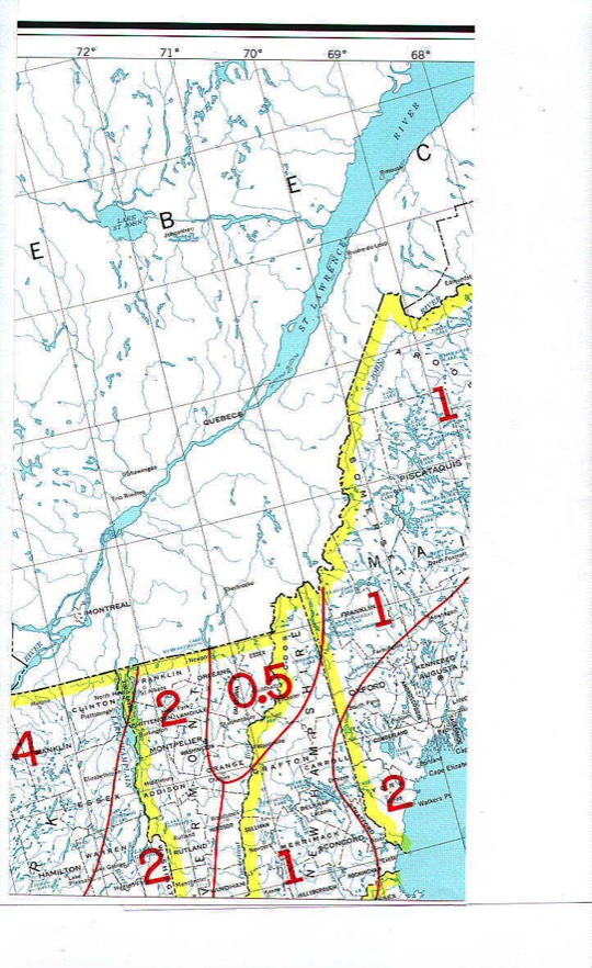
Figure 3. Soil conductivity for New Hampshire
I grew up in Illinois just north of the Illinois River valley. Most of the state of Illinois is on a flood plain, and the soil is deep and richly dark, perfect for growing corn and soybeans. Getting flooded with nutrients every few hundred years has made the soil very conductive. Most of the state gets and 8 mhos per meter (8 times better than New Hampshire), but the Illinois River flood plain is a whopping 15 mhos per meter. That’s very rich soil, indeed.
The point of this is to understand we here in New England need to be a little more diligent about our ground systems than those living in a flood plain. Every inch our RF current needs to crawl across the soil adds to our losses. The difference between a current traveling along the ground and one traveling in a wire is huge: from 1000 ohms per meter for the soil, and nearly zero ohms per meter for a copper wire. We probably can’t create an enormous copper disk extending out several wavelengths for our vertical, but we can do something to reduce that resistance in the ground.
Radials
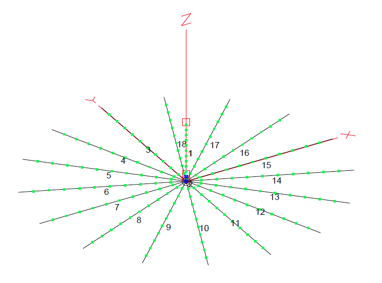
Figure 4. Vertical antenna with 16 radials
I picked the number sixteen for this example, but the number of radials one should use in a particular situation is subject to debate. The ARRL Antenna Book has a whole section on the effects of ground, and this paper from Rudy Severns, N6LF, goes through some experiments where he varies the number of radials and sees the effects.
Here’s the short version: adding radials (up to about sixteen radials) gives you a somewhat linear improvement to your signal strength. Using 0 dB for a baseline of no radials (just depending on ground conductivity), a system with 16 radials will be about 2 dB better. Remember, 3 dB is approximately a doubling of power, so this is a significant improvement. More than sixteen provides a small improvement with each additional wire, with sixty-four radials yielding about a 2.5 dB improvement over the raw ground.
Why? What is happening with those radials? To answer that we need to think like an RF current. We leave the vertical radiator and look for a return path through the ground back to the radio. If we meet a wire in this direction then that return path is optimal, with low resistance. Current always seeks the least resistance. But what happens if we are careening off in a direction where there is no wire?
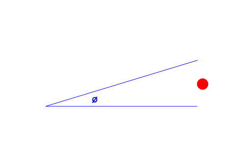
Figure 5. Radial wires with an RF current landing between them
sin(22.5-degrees) * 33-feet = 12.6-feet
That’s roughly 4-meters. If our signal lands between these wires (as illustrated by the red dot in figure 5) then it would have to travel at least 2-meters to find one wire or the other. The total resistance encountered in that journey will be more than if it landed directly on one of the radials, but a meter or two versus ten meters is an improvement. And, things are even better as we get closer to the antenna since the distance between the wires gradually reduces until they meet in the middle under the antenna.
Adding more radials would make the distance between the ends smaller, but the law of diminishing returns enters the scene as eventually reducing the distances between ends only makes a small change in the overall resistance the current encounters.
How long should radials be?
The answer is fifteen quarter-wave radials of 33-feet are better than eight half-wave radials at 66-feet. Even better, as it turns out, is thirty-two eighth-wave radials of about 16-feet. The differences aren’t much, just a few tenths of a dB, but the data clearly trends one direction: more radials even if you sacrifice length (so long as they are at least an eighth-wave long).
This might go back to figure 5. It is the gaps between the wires that causes losses. If you minimize the gaps, even if it is just for the close-in part of the radial array, the current flows better.
How many radials should I install?
I installed a SteppIR Vertical BigIR antenna system a few years ago. It is a vertical antenna that needs a radial field. To simplify things, I bought the DX Engineering radial plate shown below.
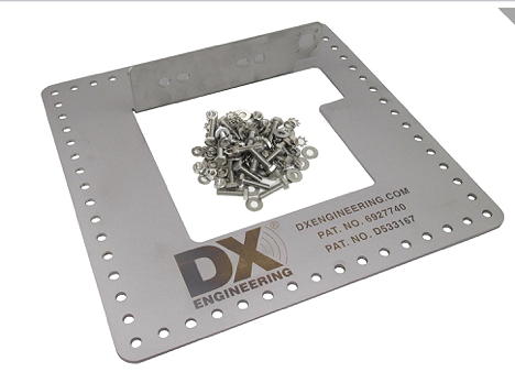
Figure 6. The DX Engineering radial plate
My house is on a rise with a French drain that routes water away from the foundation and into a low-point in my lawn. That area is always damp, if not soaking wet, and was perfectly positioned to hold my new antenna. I gambled that the lush, wet soil would be a better conductor than the dry, sandy stuff in other areas of the yard.
The lowest band that the antenna supported was 80m, so I designed my radial field for that band knowing that the field would perform even better when used with shorter wavelengths. A quarter-wave of 80m is about 66-feet. Going with the analysis from the ARRL Antenna Book, I decided against installing 66-foot radials and instead opted for twice as many eighth-wave length radials.
The book showed that the difference between thirty-two radials at that length and sixty-four was minimal. Even so, I managed to get 60 radials into the ground. Why so many when the book indicated that the performance wouldn’t be improved much over the thirty-two radial configuration? I put those extra radials in knowing that some of the radial wires would become damaged over the years. I knew that animals were attracted to that damp area. I’ve done some stupid things with the string trimmer, too. Years later, the radial field performs, probably because I added a safety factor of radials during the installation.
Evolutionary considerations
If I knew then what I know now, I’d put a very serious piece of metal in the ground, one that could hold up a big, heavy antenna if I so chose. Perhaps some of you will learn from my mistake.